 English

Views: 0 Author: Site Editor Publish Time: 2026-09-14 Origin: Site


A machine trial acts as the ultimate proof-of-concept before significant CapEx deployment or long-term outsourcing commitments. Companies stake massive budgets on these evaluations. They expect clear, objective validation of equipment performance and production viability. However, reality often falls short of these expectations due to a simple oversight.
Most trial delays and perceived machine failures rarely originate from actual mechanical faults. Instead, they stem from unverified discrepancies between physical empty tube samples, digital artwork specifications, and machine sensor requirements. These blind spots quickly turn validation exercises into chaotic troubleshooting sessions. Engineers spend hours diagnosing material flaws rather than testing equipment limits.
We must fix this approach. This article provides a strict pre-trial verification framework. You will learn how to prepare correctly, ensuring your trial accurately validates machine capability rather than wrestling with basic material and design errors. Proper preparation guarantees your evaluation yields dependable data for smart purchasing decisions.
Optical sensor registration (eye marks) and unprinted sealing areas must be mathematically aligned with the machinery's indexing capabilities before printing physical trial samples.
Physical tube specifications—especially material composition and wall thickness—dictate whether thermal or ultrasonic sealing will yield compliant burst strengths.
A successful trial requires defining objective go/no-go criteria, including volumetric accuracy tolerances, seal integrity metrics, and aesthetic limits for crimp distortion.
Documenting material variances during the trial is critical for finalizing the configuration of production-scale equipment.
Digital 3D renders look flawless on modern computer screens. They completely ignore the physical realities of crimping, sealing, and material memory. When digital artwork meets a physical sealing jaw, reality sets in fast. Graphic designers frequently forget how plastic tubes distort under high pressure. They place intricate text directly over fold lines. This digital-to-physical gap ruins trials before they even begin. We must bridge this gap by enforcing strict engineering limits on creative artwork files prior to printing physical samples.
Incorrect tube samples routinely destroy otherwise perfect trials. For example, an out-of-spec wall thickness behaves unpredictably under rapid heating. This inconsistency makes high-quality tube filling and sealing machines appear fundamentally defective. Evaluators mistakenly blame the equipment. The real culprit is the non-compliant material absorbing heat unevenly. Flawed purchasing decisions inevitably follow these false negatives. Buyers reject capable machinery and choose inferior options, unaware they based their decision on bad sample inputs.
Halting a machine trial drains corporate budgets incredibly fast. Technical engineering teams stand idle while you investigate the problem. You must rapidly re-order custom empty tubes from your supplier. Rushed manufacturing and overnight shipping fees compound the financial loss. Furthermore, rescheduling the trial throws entire project timelines off track. Delayed trials push back product launch dates, costing brands valuable market share. Proper pre-trial validation eliminates these massive resource drains entirely.
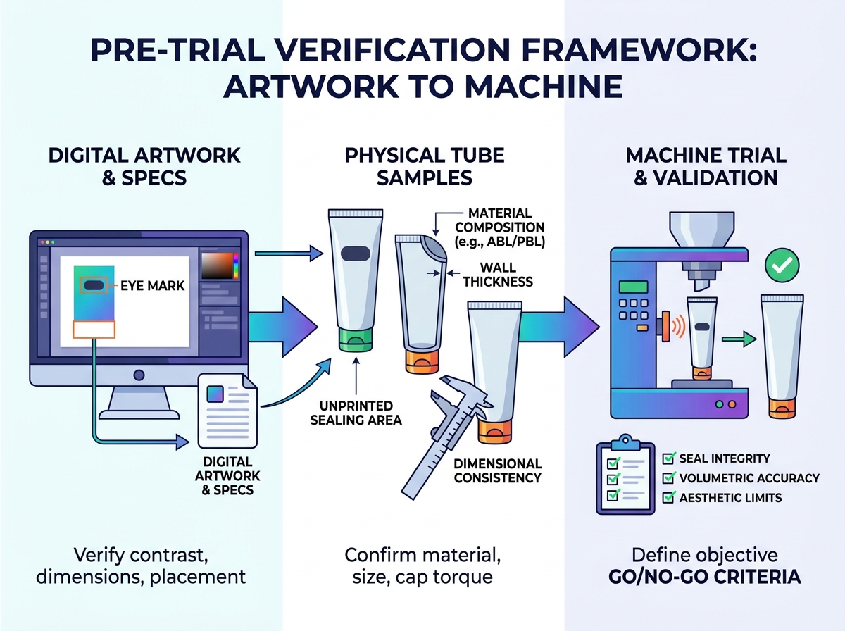
Standard photoelectric sensors require absolute precision to index tubes correctly. You must define exact contrast requirements early in the design phase. An industry-standard eye mark measures at least 2mm wide by 5mm long. Place it strategically at the base of the tube for accurate optical sensor detection. Highly reflective metallic inks cause severe reading problems. They bounce light back irregularly, blinding standard sensors. Always use matte, dark colors like black or dark blue against a light background. This creates the stark contrast needed for high-speed automated indexing.
You must establish a mandatory blank space at the tail of every tube. Ink located in the seal zone actively compromises molecular bonding. Chemical pigments interfere with the melting plastic. This fundamental rule holds true whether you use traditional hot-air systems or advanced ultrasonic tube filling equipment. Clean, unprinted zones ensure pristine seal integrity. If graphics bleed into the sealing area, you will experience micro-leaks during burst testing. Always instruct your printer to leave a minimum clearance zone free of varnish and ink.
Sealing compression violently distorts artwork. Keep all critical typography away from the crimping area. Logos placed too close to the top will stretch and crack uncontrollably. High heat and extreme pressure warp printed design elements permanently. Set clear dimensional boundaries in your die-line files to prevent illegibility. A good rule of thumb is keeping barcodes, batch numbers, and logos at least 15mm away from the ultimate seal line. This protects brand aesthetics during the violent compression phase.
Use solid black or dark navy for the registration eye mark.
Ensure a strict 15mm unprinted zone at the open tail end.
Avoid UV gloss coatings in the designated sealing area.
Keep regulatory text well below the expected crimp line.
Test a small digital print run before ordering full trial batches.
You must outline the required documentation for your tube composition before the trial. Identify clearly if you use Mono-layer PE, Co-extruded, Aluminum Barrier Laminate (ABL), or Plastic Barrier Laminate (PBL). Material type directly dictates your sealing technology selection. Aluminum strictly requires mechanical folding and crimping. Laminate or solid plastic structures necessitate heat or ultrasonic welding. Matching the wrong material to the wrong sealing jaw guarantees a failed trial. Review the material spec sheet with your machinery vendor immediately.
Material Composition vs. Sealing Technology Matrix
Tube Material Type | Recommended Sealing Technology | Common Vulnerabilities During Trials |
|---|---|---|
Mono-layer PE (Polyethylene) | Hot-Air / Thermal Sealing | Prone to wall-thinning if heat time is too long. |
Aluminum (Metal) | Mechanical Fold & Crimp | Metal fatigue and cracking if folded incorrectly. |
ABL (Aluminum Barrier Laminate) | High-Frequency or Hot-Air | Exposed foil edges can cause aesthetic burning. |
PBL (Plastic Barrier Laminate) | Ultrasonic or Hot-Air | Delamination if the temperature profile spikes. |
Dimensional variance destroys continuous trial runs. Verify your trial batch matches the exact production dimensions perfectly. Both the diameter and the length must remain highly uniform across the entire batch. This consistency ensures sizing parts, like pucks and holders, fit the tubes exactly. Even a millimeter difference in diameter causes tubes to jam in the indexing carousel. Minor length variations confuse the filling nozzle dive depths. Always demand a dimensional inspection report from your supplier prior to shipping.
Caps demand strict attention during trial preparation. Confirm your suppliers pre-torque them to actual production standards. Properly tightened caps allow accurate equipment calibration. Loose caps cause the tube to spin loosely in the puck during indexing. Filling nozzles rely on a stable tube base for correct diving depth. Precise depths prevent product stringing and enable clean blow-off at the end of the fill cycle. Validate orifice sizes to match the viscosity of the test product.
A fifty-tube sample proves absolutely nothing about production readiness. It creates a sanitized, highly unrealistic scenario. You need a statistically significant batch to evaluate actual performance. Running 500 to 1,000 tubes allows you to measure actual Overall Equipment Effectiveness (OEE). This prolonged run uncovers true operational hiccups over time, such as heat jaw drift or indexing timing errors. It separates reliable machinery from equipment that only performs well during brief, heavily supervised bursts.
You must define specific empirical tests required post-trial. Perform rigorous burst testing to measure the internal pressure tolerance. Apply vacuum leak testing protocols, submerging sealed tubes in water under negative pressure. Execute peel testing to visually analyze the polymer bond strength. These scientific methods verify your seal against strict industry compliance standards. Visual inspections are insufficient. Rely entirely on documented physical tests to confirm the machine executed a flawless molecular weld.
Many brands lack dedicated in-house engineering teams capable of auditing complex trials. Using custom packaging machinery services for Factory Acceptance Testing (FAT) solves this vulnerability completely. These professionals provide highly objective, third-party validation. They translate raw trial data into actionable engineering insights. Expert technicians spot micro-inconsistencies you might miss. They challenge the machinery vendor constructively, ensuring the equipment meets all functional specifications before you sign the final acceptance documents.
Look strictly at your pre-defined success criteria. Did the machine hit the zero-defect seal rate above 99.5 percent? Did it maintain the target output speed throughout the entire 1,000-tube run? Assess these metrics objectively without emotion. If the equipment required constant tweaking to maintain accuracy, it failed the outcome fit. The trial data should prove the machine operates autonomously within your required tolerances.
Realistic trials often involve multiple artwork SKUs. They might also include different tube sizes and cap styles. Evaluate the exact time required for these changeovers. Note any special tooling or tools needed by the operator. A fast machine loses its advantage if size changeovers take four hours. Measure how intuitively the software handles recipe changes. Fast, tool-less changeovers signify a highly scalable, modern equipment design.
Transitioning from the trial phase to contract execution requires extreme discipline. Create a strict, step-by-step checklist to formalize the decision.
Verify all volumetric accuracy logs meet the required fill tolerances.
Confirm all burst and vacuum tests passed industry standards.
Document any minor material variations noted during the run.
Ensure all documented risk factors are accounted for in the build sheet.
Obtain signatures from your quality assurance lead and the machinery vendor.
Following this checklist guarantees you only purchase equipment proven to handle your specific physical materials and production demands.
Meticulous pre-trial confirmation of artwork and physical samples fundamentally protects the integrity of your evaluation process. Without verifying eye marks, material compositions, and dimensional tolerances, you waste time troubleshooting basic supply errors instead of testing machinery limits. Always define strict, objective success criteria before the trial begins. We advise decision-makers to mandate signature approvals on physical tube proofs from both the packaging supplier and the machinery vendor. Only schedule the formal trial after confirming every physical parameter aligns perfectly with the machine’s sensor and sealing requirements.
A: The industry standard for a tube registration mark is typically 2mm wide by 5mm long. High contrast against the background color is absolutely necessary. This distinct contrast allows the optical sensors to detect the mark reliably, ensuring accurate indexing and rotational alignment before filling and sealing.
A: Cracking occurs due to the interaction between heavy ink coverage, UV gloss coatings, and the physical pressure of the sealing jaws. The intense heat and mechanical compression stretch the polymer. If brittle inks sit directly on the seal line, they fracture and flake off instantly.
A: Not always. Hot-air systems blow external heat onto the tube walls, requiring careful thermal management to avoid scorching external inks. Ultrasonic sealers generate internal molecular friction to melt the plastic, keeping the outside relatively cool. Both require ink-free sealing zones to guarantee strong molecular bonds.
A: You should supply a pragmatic estimate of 1,000 to 2,000 empty tubes per format. This quantity provides enough material for initial mechanical setup, precise calibration, a continuous production run to test OEE, and a comfortable contingency buffer for unexpected troubleshooting.


