 English

Views: 0 Author: Site Editor Publish Time: 2026-10-30 Origin: Site


Procuring high-speed packaging equipment carries significant operational risk when mechanical capabilities do not align with consumable material specifications. An otherwise high-performing machine often experiences chronic downtime, persistent label skewing, or frustrating sensor faults. These issues usually emerge if the label roll's core, web width, gap size, or unwind direction is mismatched to the applicator's hardware. Buying standalone hardware without auditing your label supply chain creates immediate production bottlenecks.
This article provides a definitive framework for evaluating equipment compatibility against established labeling consumable standards. We outline exact tolerances for core diameters, winding protocols, and sensor indexing thresholds. By following this technical guide, you ensure seamless integration from early procurement discussions all the way to final production runs. You will learn how to align physical roll dimensions and orientation requirements, avoiding costly post-installation modifications while maintaining reliable throughput.
Core & Diameter Tolerances: Standardizing on a 3-inch (76mm) core with a strictly defined maximum outside diameter (OD) prevents web tension failures and mandrel incompatibility.
Winding Protocols: Specifying the correct unwind direction (Industry Standards #1 through #8) is non-negotiable for proper orientation on automated applicators.
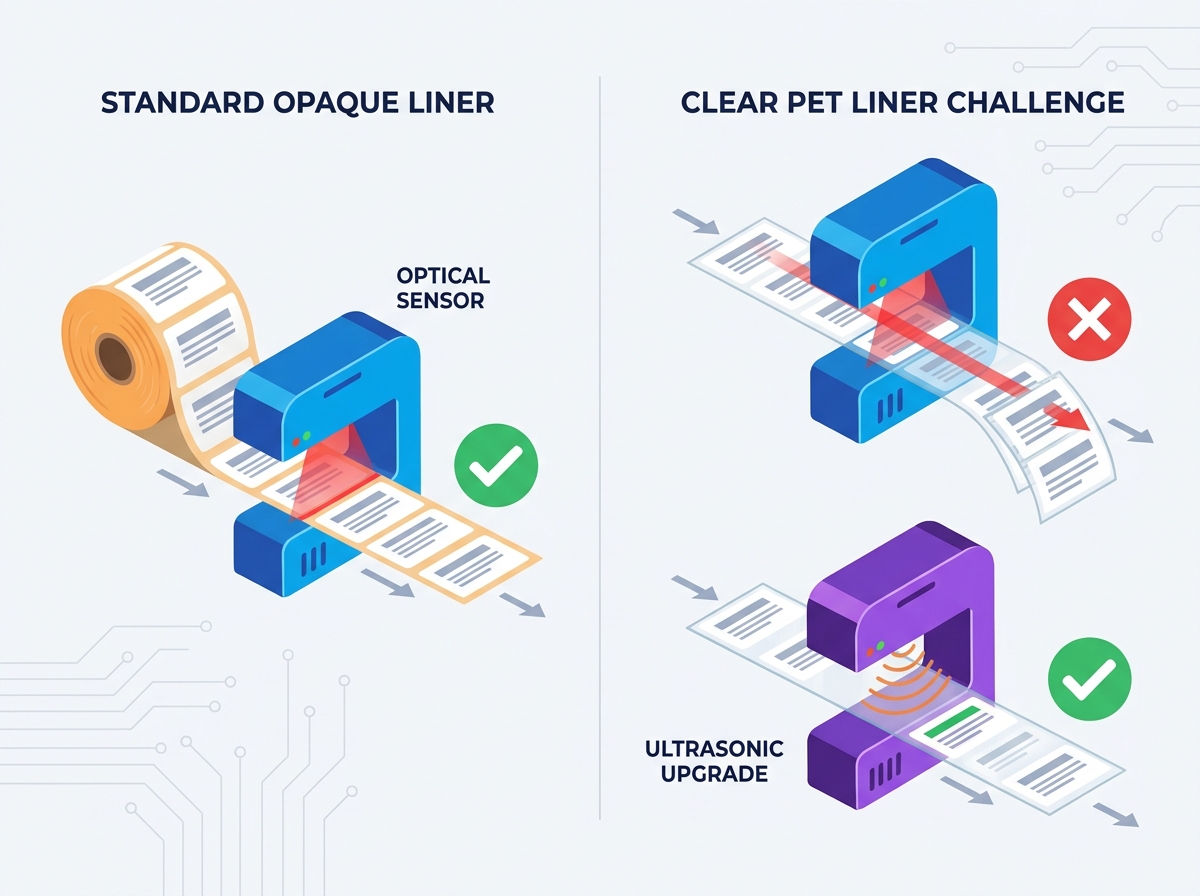
Sensor Dependencies: A standard 2.5mm to 3mm gap between labels is mandatory for optical indexing; clear liners require ultrasonic sensor upgrades.
Validation Mandates: Physical container and label samples are critical for Factory Acceptance Testing (FAT) to prove compliance and calculate true throughput.
Buyers frequently isolate machine evaluation from material procurement. However, evaluating bottle labeling machines requires a simultaneous audit of your facility’s current label supply chain. You cannot evaluate a mechanical applicator in a vacuum. The hardware relies entirely on the quality, format, and physical dimensions of the incoming label roll. A perfectly engineered machine will fail repeatedly if fed substandard or incorrectly formatted materials.
We must define clear success criteria before installing new equipment. A successful deployment is measured by the complete absence of web snapping during operation. You want zero skipped containers on the conveyor belt. You also need sustained OEE (Overall Equipment Effectiveness) operating consistently at the manufacturer's rated speeds. Anything less indicates a disconnect between your consumables and your hardware mechanics.
To mitigate integration risks, define allowable material tolerances before shortlisting equipment vendors. This proactive approach prevents costly post-installation machine modifications. If you delay this audit, you risk receiving equipment unable to handle your specific label stock. Establish strict rules for your print suppliers. You must dictate exactly how they spool, package, and deliver your labels. This simple alignment early in the project prevents months of troubleshooting on the factory floor.
The industry baseline for automated machinery is the 3-inch (76mm) inner core. Smaller cores, such as 1-inch or 3/4-inch formats, are generally restricted to tabletop units or semi-automatic desktop machines. You must specify the core material thickness clearly to your supplier. Choosing between standard cardboard or heavy-duty plastic cores determines how well the machine's expansion mandrels grip the roll. A weak cardboard core will crush under the pneumatic tension of a high-speed applicator. This crushing effect causes the roll to wobble, leading directly to label skewing.
Next, you must evaluate the machine's physical housing limits to calculate the maximum outside diameter (OD). Most industrial labelers accept a maximum OD of 300mm to 350mm. Implementation reality often conflicts with purchasing desires. Buyers want massive rolls to reduce changeover frequency. However, exceeding the machine’s OD limit causes severe motor strain on the unwind disc. A heavy, oversized roll carries massive rotational inertia.
When the indexing motor suddenly pulls a heavy roll, the resulting tension spike causes micro-tears in the backing liner. These tears eventually cause the entire web to snap mid-production. Establish a strict maximum roll length alongside your print suppliers based entirely on this geometric limit. Never push the OD boundary beyond the manufacturer's stated maximum capacity.
Table 1: Standard Roll Specifications and Application Context
Core Inner Diameter | Typical Max OD | Preferred Core Material | Equipment Match |
|---|---|---|---|
3-inch (76mm) | 300mm - 350mm | Thick Cardboard / Plastic | High-Speed Automatic Applicators |
1-inch (25.4mm) | 150mm - 200mm | Standard Cardboard | Desktop / Semi-Automatic Units |
3/4-inch (19mm) | 100mm - 120mm | Lightweight Cardboard | Handheld Dispensers |
Industrial label printing recognizes an established eight-standard framework for rewind positions. For example, Position 1 indicates the top of the label dispenses first. Position 3 means the right side of the label dispenses first. These industry standards are universally accepted across all commercial print houses. You must specify your required position code on every single purchase order.
The chosen unwind direction must perfectly match the applicator's mounting position. Equipment designers configure hardware for either left-hand or right-hand feed paths. This orientation becomes especially critical within a broader liquid filling capping and labeling line. You cannot easily flip a roll or reverse a web path once the machine footprint is bolted to your factory floor. The hardware relies on precise geometric alignment to function.
Sourcing rolls with an inverted unwind direction results in immediate production failure. The machine will apply labels upside down or backward on your containers. To prevent this, confirm the OEM’s required chart position in writing prior to ordering initial consumable batches. We recommend following a strict verification sequence before greenlighting material production.
Request the official unwind chart diagram from your machinery manufacturer.
Identify your specific applicator orientation (left vs. right feed).
Match the feed orientation to the corresponding standard position (1 through 8).
Submit this specific position number to your label converter as a hard requirement.
Request a small prototype roll to physically test the unwind path before ordering bulk quantities.
The space between individual labels acts as a physical trigger for the automation system. This "gap" signals the machine to stop dispensing at the exact right moment. You must evaluate equipment based on its sensor response time relative to this gap size. High-speed lines require incredibly precise gap spacing to trigger sensors without micro-delays.
You must maintain a strict 2.5mm to 3.0mm gap between every label. Variances greater than 0.5mm will cause application drift. When the gap fluctuates, the machine miscalculates the stopping point. This calculation error means labels get applied progressively higher or lower on the bottle as the run continues. Consistent die-cutting at the printing facility is the only way to prevent application drift.
Standard photoelectric sensors rely entirely on opacity differences between the label and the liner. They shine a light through the gap to register a break in the material. However, if your labels utilize a clear PET backing liner, optical sensors will fail. The light passes right through both the label and the liner seamlessly. Your machine evaluation must explicitly require ultrasonic or capacitive gap sensors if you plan to run clear-on-clear materials.
Chart 1: Sensor Type vs. Liner Material Compatibility Summary
Sensor Technology | Paper Liner | Clear PET Liner | Metallic / Foil Labels |
|---|---|---|---|
Standard Optical | Highly Compatible | Fails (Light passes through) | Compatible |
Capacitive | Compatible | Highly Compatible | Fails (Interference) |
Ultrasonic | Highly Compatible | Highly Compatible | Highly Compatible |
Equipment specifications on paper cannot account for complex real-world variables. Glass seam variations, plastic static charge, or aggressive taper angles often disrupt perfectly calculated math. A bottle might look perfectly cylindrical on a CAD drawing, but physical manufacturing processes introduce subtle surface defects. These defects change how a label adheres to the substrate.
When evaluating a round bottle labeling machine, standard operating procedure requires proactive physical testing. You must send unapplied label rolls and 50 to 100 physical empty bottles directly to the OEM facility. Their engineering team needs these exact items to calibrate the system properly. Simulating a run with generic bottles completely invalidates the calibration process.
The Factory Acceptance Testing (FAT) phase carries specific technical objectives. You must prove the applicator's peel-plate angle smoothly transitions the label onto the sample bottle without hesitation. You must also validate that wrap-around belts apply adequate pressure without crinkling the material. This physical validation separates reliable machinery from poorly calibrated hardware.
Use strict shortlisting logic when choosing your vendor. Eliminate any manufacturer who guarantees performance without requesting physical material samples for pre-shipment calibration. Proper validation protocols protect your investment. Follow these FAT guidelines to ensure success:
Run a continuous test of at least 50 bottles at the maximum rated speed.
Inspect the backing liner for micro-tears after passing the peel plate.
Measure the placement accuracy on the bottle to ensure no vertical drift occurs.
Test the machine's recovery sequence after simulating a web break.
Verify the sensor accurately detects gaps across the entire sample roll.
Bottom-line hardware performance is entirely dependent on strict adherence to consumable material limits. You cannot out-engineer bad label stock. A high-speed applicator simply exposes the flaws in your roll winding, gap spacing, and core sizing. By respecting the geometric and physical limits of your equipment, you guarantee smooth operational throughput.
Your immediate next step requires an audit of your existing label inventory. Check your current rolls for correct core size, maximum OD, specified unwind direction, and precise gap width. Consolidate these exact metrics into a standardized Spec Sheet. Include this critical data directly in your next equipment Request for Proposal (RFP). This transparent alignment between your consumables and your hardware ensures absolute reliability on the production floor.
A: The roll will physically scrape against the machine chassis, instantly altering web tension. This severe tension spike causes the backing paper to snap. It can also cause the stepping motor to stall or the indexing sensor to miss the gap entirely, resulting in constant line stoppages.
A: It can only do so if equipped with a capacitive or ultrasonic sensor. Standard optical sensors cannot differentiate between a clear label and a clear liner. This limitation results in continuous, uncontrolled dispensing. Always specify your liner material early to secure the correct sensor technology.
A: Dimensions do not capture critical real-world details like surface friction, unpredictable mold seams, or slight tapers. Physical samples allow engineers to adjust the peel plate clearance and fine-tune wrap-belt tension. This hands-on calibration prevents bubbling and skewing before the machine ever leaves the factory.


